
Workshop companion / version 2.0
One guide. The right checks.
A phone-size reference for aftermarket head units, amps, subwoofers, factory LOCs, cameras and safe garage power. Use the app to plan and document installations. Exact factory wiring and fitment must still be verified with a vehicle-specific manual or fitment provider.
Begin with your exact vehicle
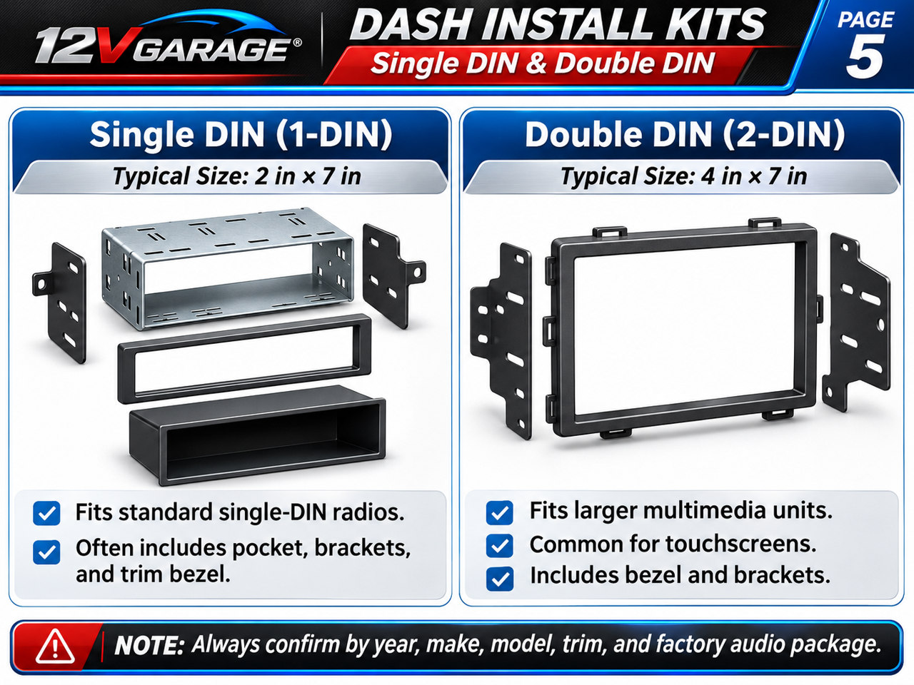
Use the fitment websites below to find an exact dash kit and wiring harness. Do not use a generic factory wire-color chart.
Quick navigation
Vehicle-specific installation lookup
Use your exact year, make, model, trim, factory amp and audio package to check installation parts and unusual factory electronics. This prototype has no locally verified OEM pinout database; it opens manufacturer fitment services and stores your research notes.
Vehicle entered on Home
Primary lookup sources
These catalogs must be completed on their sites; entering a vehicle here does not remotely query them.
Verified fitment worksheet
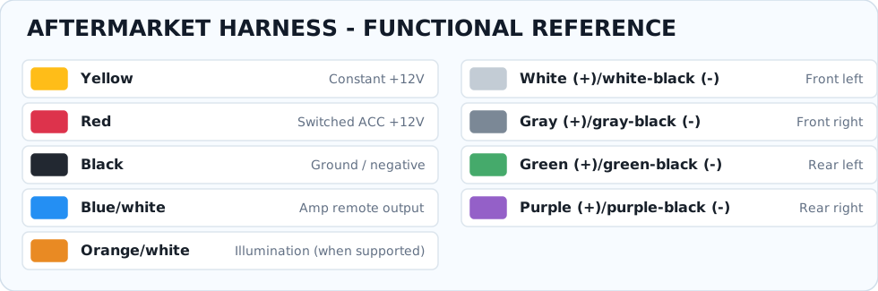
Aftermarket wire colors
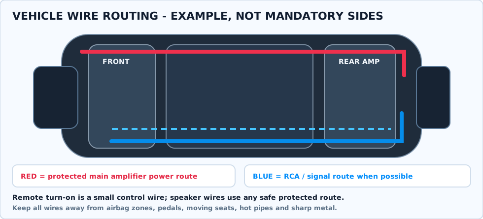
Power cable and ground
| OFC gauge | Illustrative 16–20 ft fuse example* |
|---|---|
| 10 AWG | 25A |
| 8 AWG | 60A |
| 4 AWG | 100A |
| 1/0 AWG | 250A |
*Examples, not a design guarantee. Calculate current, length, wire material, amp manufacturer and circuit ratings. Use appropriately sized ground/negative return. Amp remote is commonly 18 AWG, not the heavy main-power gauge.
Power, ground & remote wire sizing
Estimate voltage drop in stranded copper wire, then verify allowable current/fuse rating with the cable and amplifier manufacturers. Ground or DC negative return must be properly sized too.
Voltage drop is only ONE sizing criterion. This calculator does not certify conductor ampacity, thermal safety, circuit fusing, chassis resistance or connector ratings. Select a gauge that meets BOTH the voltage-drop goal and your manufacturer's ampacity/fuse requirements. For a chassis return, the calculation covers only the entered copper sections, not the body metal.
Remote turn-on: smaller wire is normal
The amplifier REM terminal is a control signal, not the amplifier's main current supply. 18 AWG is common for a low-current 12V turn-on circuit, subject to the radio/amplifier manual and wire length. Never substitute an 18 AWG remote wire for amplifier B+ or ground.
Crutchfield's copper power/ground wire chart · Fuse-size safety information
1–4 subwoofer impedance calculator
Plan series, parallel, and symmetric series-parallel connections using identical subwoofers. Each sub's voice coils are combined first; then the subs are combined in balanced groups.
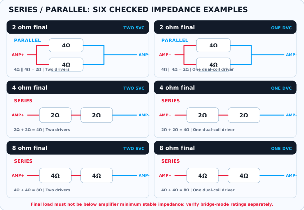
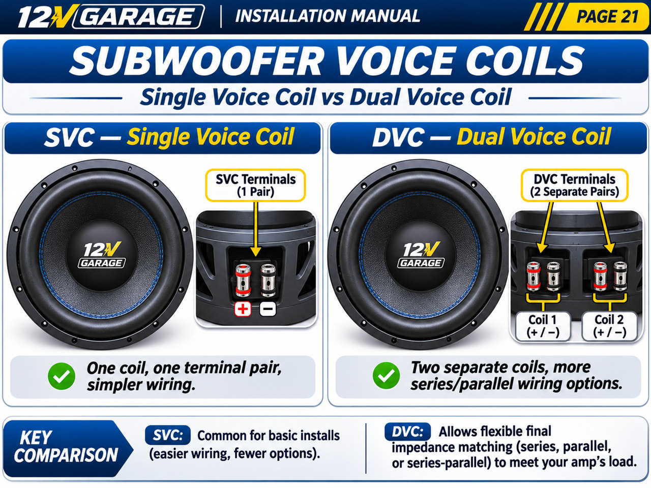
Cross-check with Crutchfield's actual subwoofer wiring diagrams.
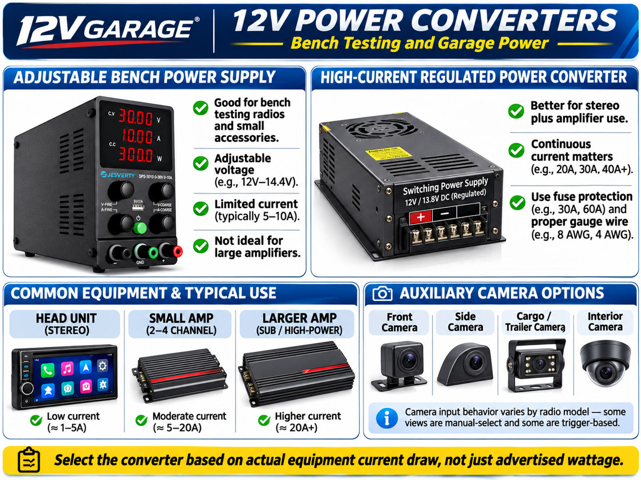
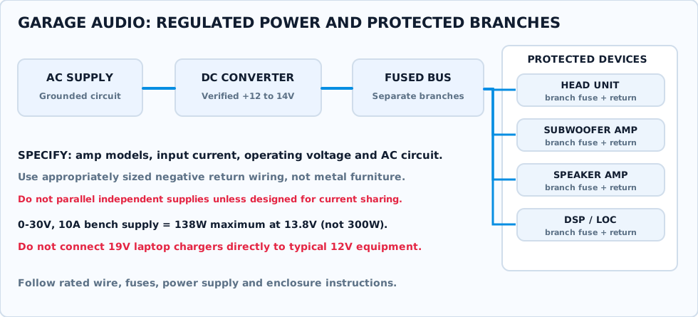
Garage DC power worksheet
For repurposed automotive equipment in a garage. Enter verified continuous input current requirements—not advertised max-wattage labels.
The 25% margin displayed below is an illustrative planning reserve, not a manufacturer requirement or assurance against music transient demands.
Multimeter installation & diagnostics
Use the proper meter input jacks and mode. This is a field reference, not a substitute for vehicle service instructions.
Before probing
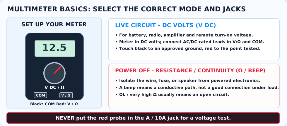
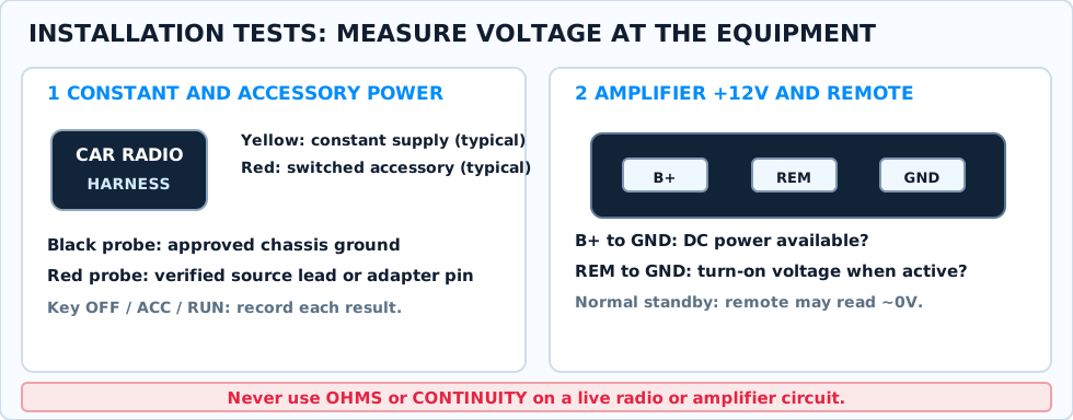
DC voltage with power ON: black lead in COM, red lead in V/Ω, DC V mode. Compare the suspect point to a verified return or specified reference.
Resistance / beep with power OFF: isolate the fuse, speaker or wiring from powered electronics before testing.
Choose the problem
Interpret the reading
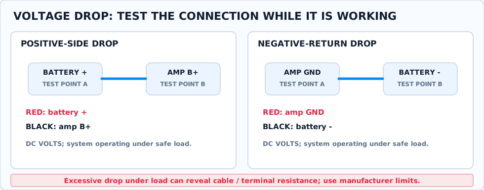
0 V on a supposed live power lead: investigate source, switch/interface, fuse or connection. OL on an isolated fuse: open circuit. Continuity beep: a low-resistance path exists, but its capacity under load is still unproven. DC speaker resistance: usually lower than nominal speaker impedance.
See Fluke continuity guidance and Crutchfield amplifier diagnosis.
Factory radio to aftermarket amp
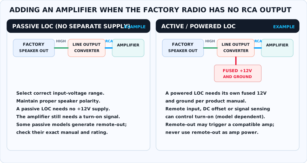
A factory receiver without preamp RCA output may use an amplifier with suitable speaker-level inputs, a passive LOC, a powered LOC or a model-specific DSP/interface. Don't assume the convenient tapped wire contains a full-range signal.
Steps before power on
- Verify speaker positive/negative and whether factory outputs are amplified, filtered or differential.
- Match the LOC input capacity to the factory signal.
- Passive LOCs have no dedicated operating +12V, but may provide a low-current remote trigger depending on model.
- Active LOCs typically require their own fused 12V and ground. Some offer signal-sensing or DC-offset turn-on.
- Connect RCA signal and rated remote output to your amplifier; check gains with EQ/boost off.
Camera installation assistant
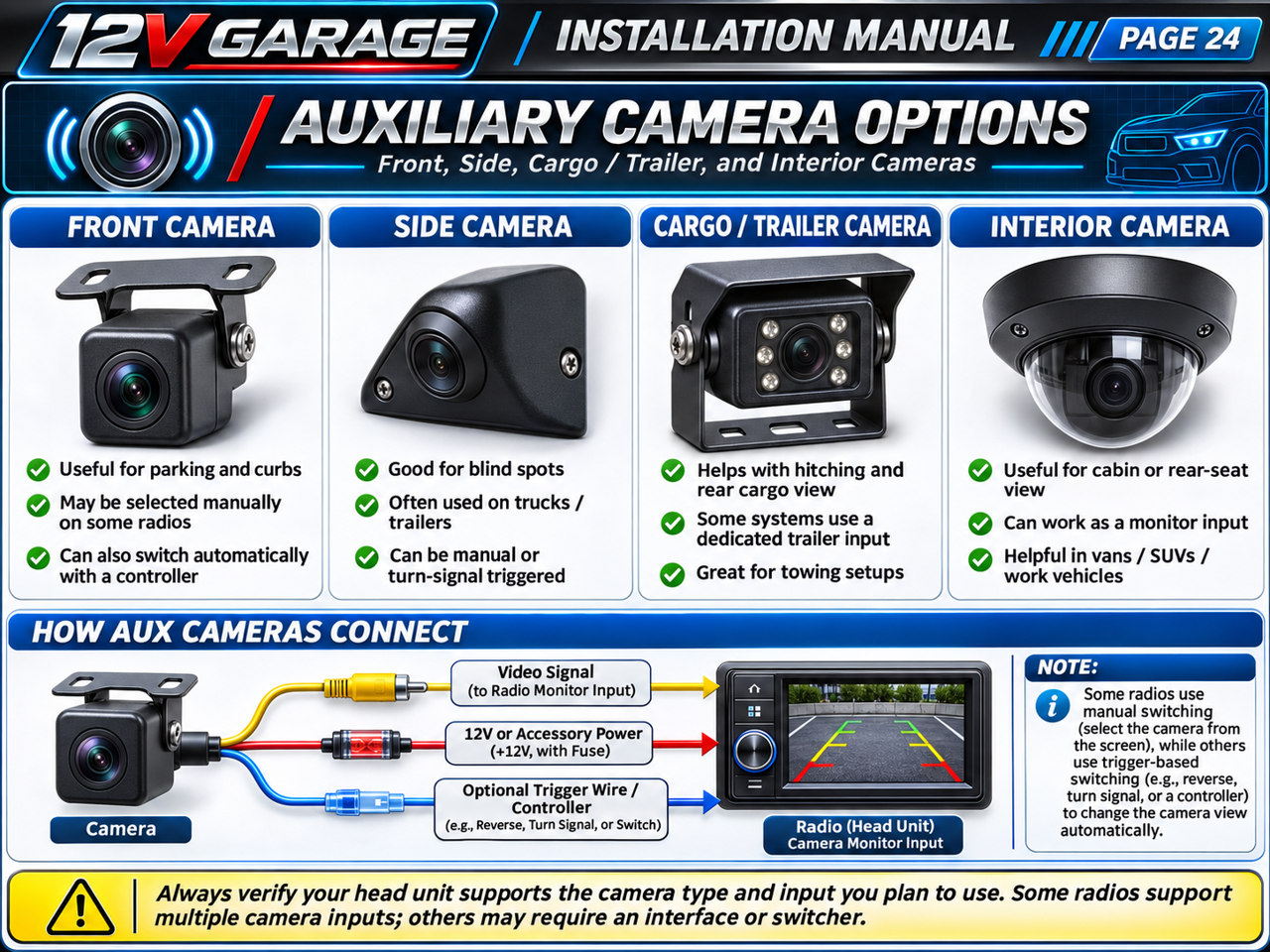
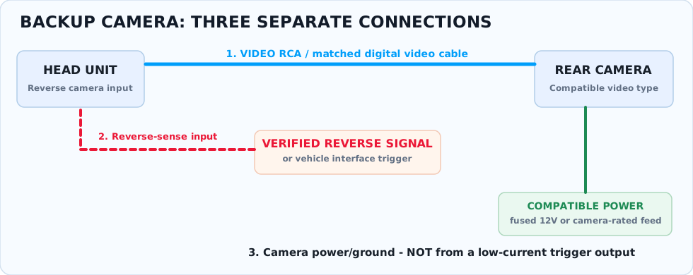
The three connections
- Camera video to the head unit's specified camera input.
- Head unit reverse trigger to a verified compatible sense lead or factory integration module.
- Camera power and ground from the correct camera-rated supply, not from a sense lead.
Tuning and rattle control
Interactive ten-band EQ preview
Move any slider to see an illustrative audio response curve. These are not calibrated filter measurements; actual radios have different EQ widths and behavior.
HPF/LPF values are visual markers only; they do not model crossover slopes. Start with EQ flat, bass boost off, and use manufacturer gain-setting guidance. Excessive bass boost may clip the signal or damage speakers.
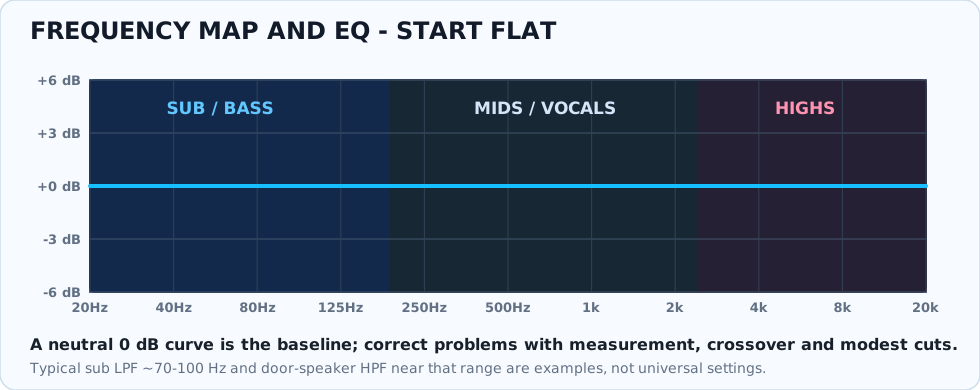
Start with a flat EQ
Sub/bass, midrange and treble are overlapping frequency regions. Keep EQ at 0 dB to begin. Example sub LPF ~70–100Hz and speaker HPF in a similar area are only starting places; match to actual drivers and crossover slopes.
For distorted bass, check gain and supply voltage rather than adding more boost. An EQ slider labeled 0.5 is not universally +3 dB.
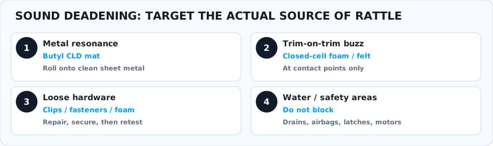
Stop the rattle where it begins
Butyl CLD damps vibrating metal, while closed-cell foam/felt decouples trim. Tighten loose fasteners and retain all door drains, window mechanisms, airbag paths and moisture barriers.
Final installation checklist
Check items as you finish. This browser remembers your selections locally on this device.
Saved installations
Keep one record per vehicle or garage project. Saves in this browser's local storage, not a cloud account. You can export a backup to a JSON file.
Your projects
0 savedPhotos are compressed to small preview images and saved with the project. Export your JSON project backup to preserve them.
Backup and transfer
Import MERGES valid project records; projects with matching IDs are replaced. Keep backups private—project notes may include vehicle information. A browser data reset can erase local projects.
Reliable technical links
Sources are externally hosted. Listings can change; confirm exact product IDs and vehicle information. Community forum posts are unverified until checked against a service manual.
Check exact fit and official manuals first
Forums for rare issues
Community experiences aren't verified wiring pinouts. Match model year, trim and exact interface, and cross-check against the manufacturer.